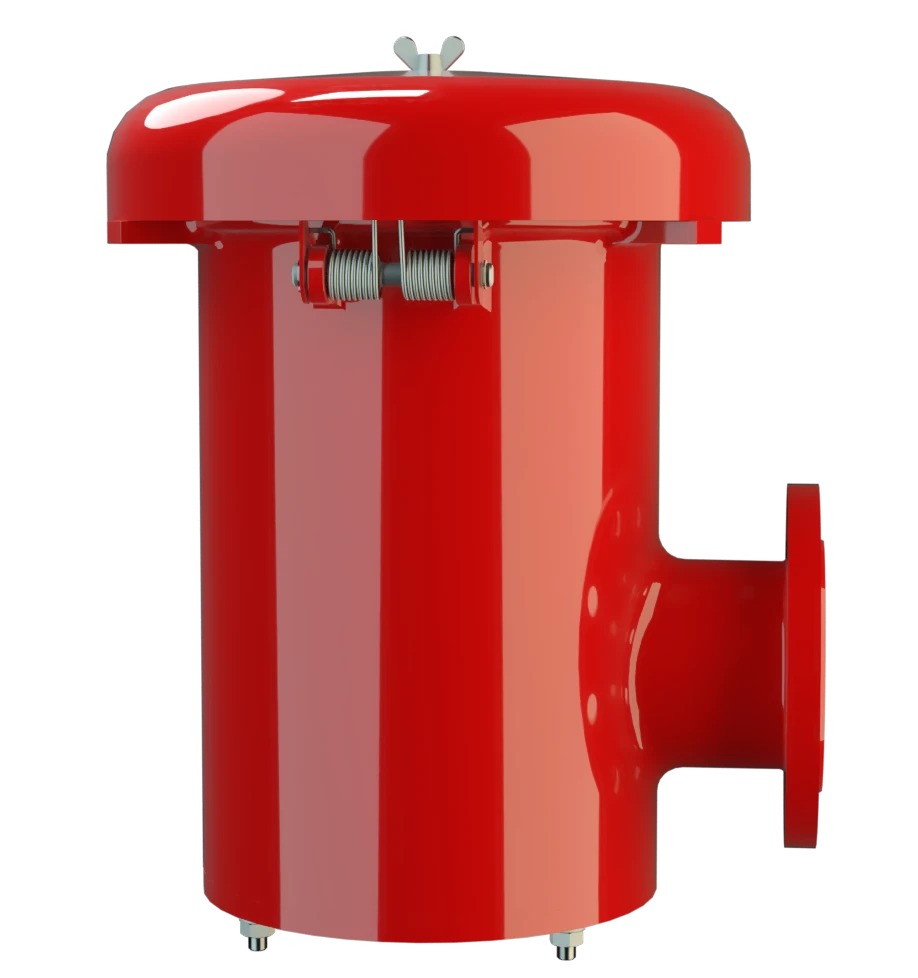
PV/ELR
Pressure and Vacuum Relief Valve
Features
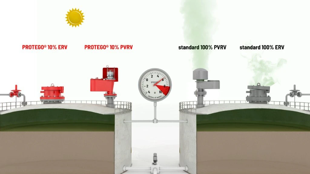
Tecnología del 10%
Extrema estanqueidad
Mantenimiento óptimo de la presión
Flujo volumétrico
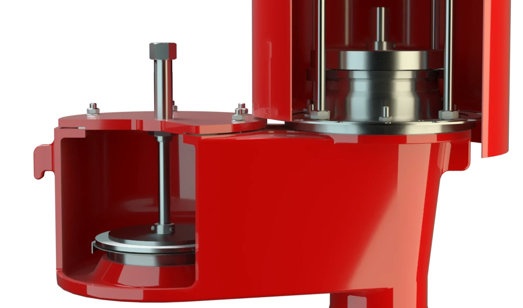
Plato de válvula guiado
Se usa en zonas con riesgo de explosión
Drenaje de condensados
Diseño compacto
Combined Pressure and Vacuum Relief Valve
Full Lift Technology
Advanced Manufacturing Technology
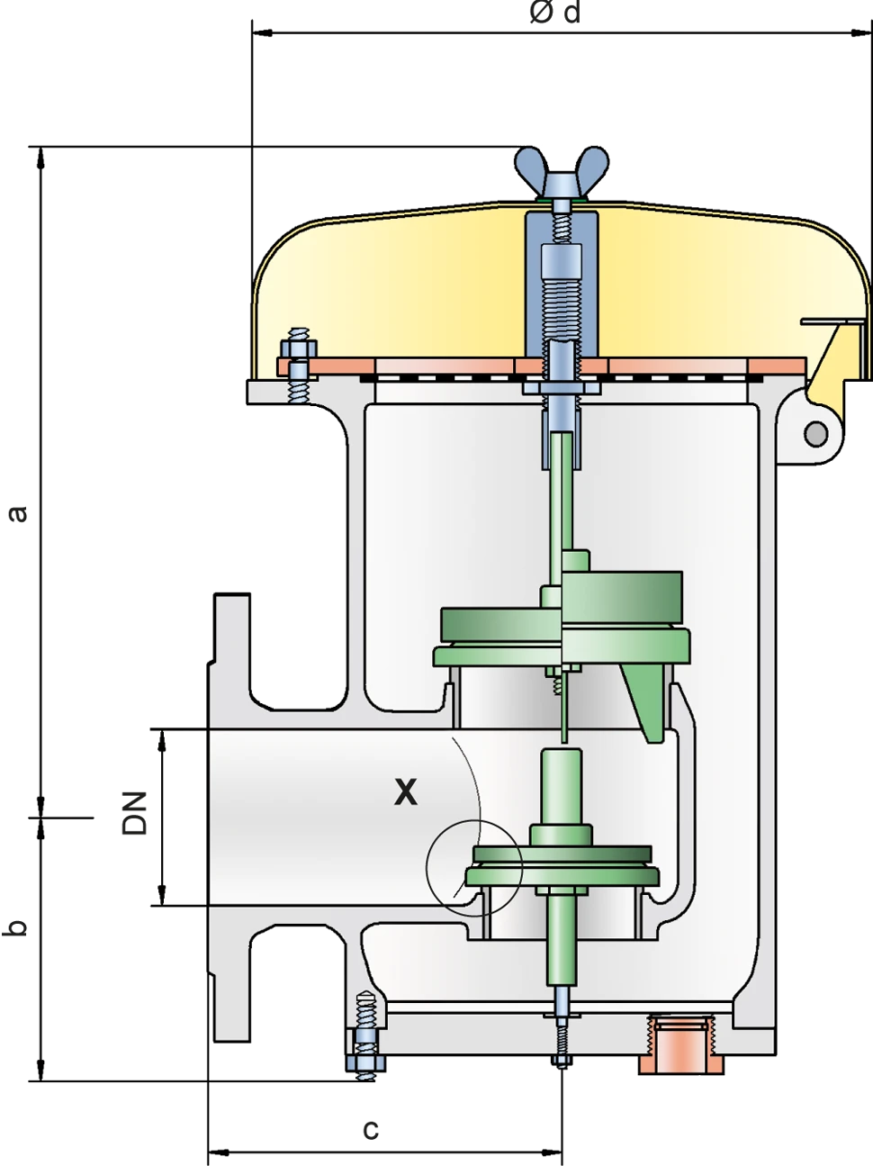
Dimensiones
To select the nominal size (DN), use the flow capacity chart on the following page
| DN | 80 / 3" | 80 / 3" | 100 / 4" | 100 / 4" |
| Set pressure | ≤ +35 mbar | > +35 mbar | ≤ +35 mbar | > +35 mbar |
| Set pressure | ≤ +14 inch W.C. | > +14 inch W.C. | ≤ +14 inch W.C. | > +14 inch W.C. |
| a | 345 / 13.58 | 475 / 18.70 | 345 / 13.58 | 475 / 18.70 |
| b | 146 / 5.75 | 146 / 5.75 | 146 / 5.75 | 146 / 5.75 |
| c | 218 / 8.58 | 218 / 8.58 | 218 / 8.58 | 218 / 8.58 |
| d | 353 / 13.90 | 353 / 13.90 | 353 / 13.90 | 353 / 13.90 |
Dimensiones en mm / pulgadas
Dimensions for pressure/ vacuum relief valve with heating jacket upon request
Selección de materiales para la vivienda
| Design | B | C |
| Housing | Steel | Stainless Steel |
| Heating jacket (PV / ELR-H-...) | Steel | Stainless Steel |
| Valve seat | Stainless Steel | Stainless Steel |
| Weather hood | Steel | Stainless Steel |
| Protective mesh screen | Stainless Steel | Stainless Steel |
Special materials upon request
Selección de materiales para la válvula de presión
| Design | A | B | C | D |
| Pressure range [mbar] [inch W.C.] | +2.0 up to +3.5 +0.8 up to +1.4 | >+3.5 up to +14 >+1.4 up to +5.6 | >+14 up to +210 >+5.6 up to +84 | >+14 up to +210 >+5.6 up to +84 |
| Valve pallet | Aluminium | Stainless Steel | Stainless Steel | Stainless Steel |
| Sealing | FEP | FEP | Metal to Metal | PTFE |
Special material as well as higher set pressure upon request
Selección de materiales para la válvula de vacío
| Design | A | B | C | D |
| Pressure range [mbar] [inch W.C.] | -3.5 up to -5.0 -1.4 up to -2.0 | <5.0 up to -14 <-2.0 up to -5.6 | <-14 up to -35 <-5.6 up to -14 | <-14 up to -35 <-5.6 up to -14 |
| Valve pallet | Aluminium | Stainless Steel | Stainless Steel | Stainless Steel |
| Sealing | FEP | FEP | Metal to Metal | PTFE |
Special material as well as higher set vacuum upon request
Tipo de bridas de conexión
| EN 1092-1; Form B1 |
| ASME B16.5 CL 150 R.F. |
other types upon request
Diagrama de flujo volumétrico
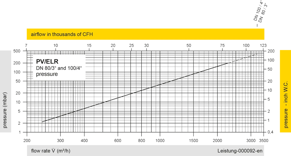
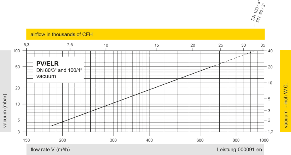
Los diagramas de flujo volumétrico han sido determinados con un banco de pruebas de caudal calibrado y certifi - cado por TÜV. El flujo volumétrico V. en [m³/h] y el CFH se refi eren a las condiciones estándar de referencia de aire según ISO 6358 (20°C, 1bar). La conversión a otras densidades y temperaturas están referidas en el Vol. 1: “Fundamentos Técnicos”.
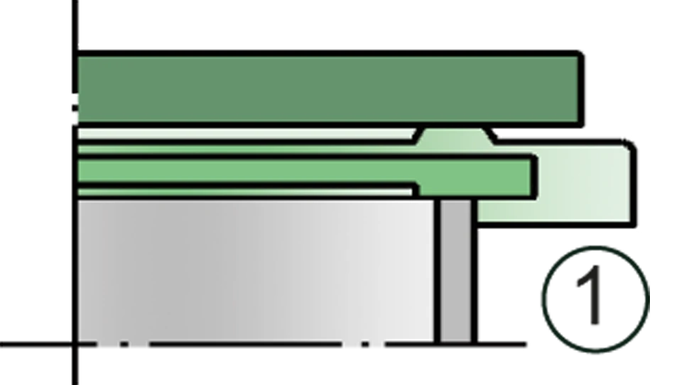
Detail X

Detail X