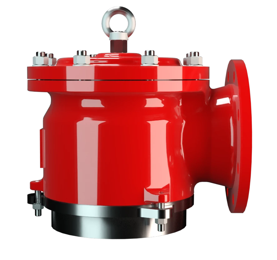
SV/E
Vacuum Relief Valve deflagration-proof
Features
Tecnología del 10%
para un aumento mínimo de presión hasta alcanzar la apertura completa
Extrema estanqueidad
Lo que se traduce en las menores pérdidas posibles de producto y en una reducción de la contaminación ambiental
Mantenimiento óptimo de la presión
Basado en la tecnología del 10 %, la presión de tarado está muy próxima a la presión de apertura para un mantenimiento óptimo de la presión en el sistema, en comparación con la tecnología convencional del 40 % o del 100 %
Flujo volumétrico
Flujo de caudal optimizado
Plato de válvula guiado
El plato de válvula va guiado dentro del cuerpo para protegerlo frente a condiciones meteorológicas adversas
Sistema de protección conforme a ATEX
Puede utilizarse como sistema de protección en zonas con atmósferas potencialmente explosivas según ATEX
Diseño modular
Permite la sustitución y limpieza de los discos de filtro FLAMEFILTER® de forma individual
Dispositivo de elevación
Disponible en un diseño especial con dispositivo de izado (para buques)
Function and Description
Main Component – PROTEGO® Flame Arrester Unit
The Deflagration-Proof SV/E Type PROTEGO® valve is a state-of-the-art vacuum relief valve with an integrated Flame Arrester Unit. It is primarily used as a device for flame transmission-proof in-breathing on tanks, containers, and process equipment. The valve offers reliable protection against vacuum and prevents in-breathing of air almost up to the set pressure; while at the same time protecting against atmospheric deflagration. The PROTEGO® Flame Arrester Unit is designed to achieve minimum pressure drop with maximum safety. The PROTEGO® SV/E valve is available for substances from explosion groups IIA to IIC.
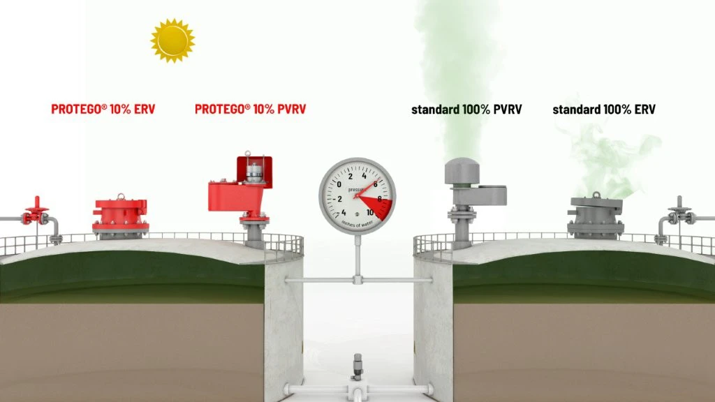
10%-Technology
When the set vacuum is reached, the valve starts to open and reaches full lift within 10% overpressure. This unique 10% technology enables a set vacuum that is only 10% above the maximum allowable working vacuum (MAWV) of the tank. After years of development, this typical opening characteristic of a safety relief valve is now also available for the low pressure range.
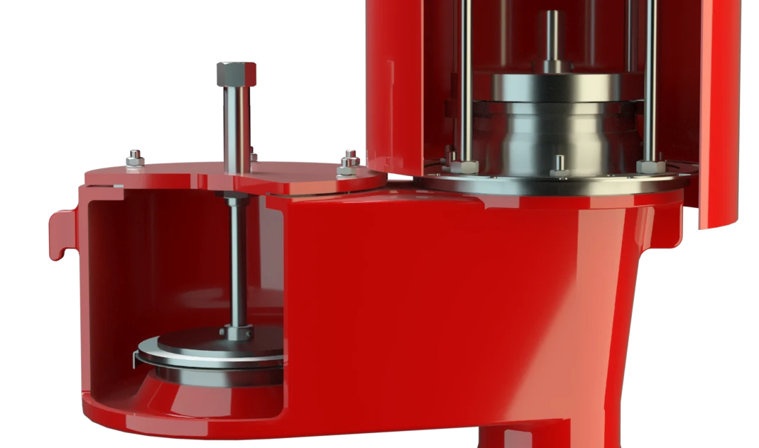
Custom Materials
The tank pressure is maintained up to the set vacuum with a tightness that is above the normal standards due to our state-of-the-art manufacturing technology. This feature is ensured by the valve seats made of high quality stainless steel and with individually lapped valve pallets (1), or with an air cushion seal, (2) in conjunction with high quality FEP diaphragm. The valve pallets are also available with a PTFE seal to prevent them from sticking when sticky substances are used and to enable the use corrosive fluids. After the vacuum is balanced, the valve re-seats and provides a tight seal.
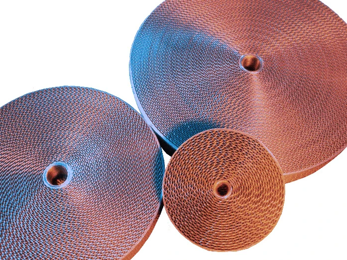
Prevents Ignition Through Integrated FLAMEFILTER®
If the valve is used in atmospheres forming an explosive mixture with air and the mixture ignites, the integrated PROTEGO® Flame Arrester Unit (3) prevents flame transmission into the tank.
The standard design is tested at an operating temperature of up to +60°C / 140°F and meets the requirements of European Tank Design Standard EN 14015 (Appendix L) and ISO 28300 (API 2000). In addition, numerous versions for higher operating temperature are available.

Many Individual Certifications
EU conformity according to the currently valid ATEX directive. Approvals according to other national/international regulations on request. Additional certificates from classification organizations for use on ships are also available.
Product Data
Dimensiones
To select the nominal size (DN), please use the flow capacity chart on the following page
| DN | 50 / 2'' | 80 / 3'' | 100 / 4" | 150 / 6'' | 200 / 8'' | 250 / 10'' | 300 / 12'' |
| a | 140 / 5.51 | 170 / 6.69 | 190 / 7.48 | 230 / 9.06 | 300 / 11.81 | 325 / 12.80 | 425 / 16.73 |
| b | 105 / 4.13 | 115 / 4.53 | 125 / 4.92 | 165 / 6.50 | 195 / 7.68 | 230 / 9.06 | 280 / 11.02 |
| c | 225 / 8.86 | 240 / 9.45 | 320 / 12.60 | 410 / 16.14 | 460 / 18.11 | 525 / 20.67 | 575 / 22.64 |
| d | 170 / 6.69 | 235 / 9.25 | 280 / 11.02 | 335 / 13.19 | 445 / 17.52 | 505 / 19.88 | 505 / 19.88 |
| e | 215 / 8.46 | 215 / 8.46 | 255 / 10.04 | 345 / 13.58 | 435 / 17.13 | 470 / 18.50 | 635 / 25.00 |
Dimensiones en mm / pulgadas
Selección del grupo de explosión
| MESG | Expl. Gr. (IEC / CEN) | Gas Group (NEC) |
| ≥ 0,65 mm | IIB3 | C |
| ≥ 0,50 mm | IIB | B |
| < 0,50 mm | IIC | B |
Special approvals upon request
Especificación de la máx. temperatura de operación
| ≤ 60°C / 140°F | Tmaximum allowable operating temperature in °C |
| - | Designation |
higher operating temperatures upon request
Selección de materiales para la vivienda
| Design | B | C | |
| Housing | Steel | Stainless Steel | |
| Heating jacket (SV / E-(S)-H-...) | Steel | Stainless Steel | |
| Valve seat | Stainless Steel | Stainless Steel | |
| Gasket | PTFE | PTFE | |
| Flame arrester unit | B | B |
Special materials upon request
Combinación de materiales para la unidad apagallamas
| Design | B | |
| FLAMEFILTER® cage | Stainless Steel | |
| Stainless Steel |
Special materials upon request
Material selection for valve pallet
| Design | A | B | C | D | E | F |
| Vacuum range [mbar] [inch W.C.] | -2.0 up to -3.5 -0.8 up to -1.4 | <-3.5 up to -14 <-1.4 up to -5.6 | <-14 up to -35 <-5.6 up to -14 | <-35 up to -60 <-14 up to -24 | <-14 up to -35 <-5.6 up to -14 | <-35 up to -60 <-14 up to -24 |
| Valve pallet | Aluminium | Stainless Steel | Stainless Steel | Stainless Steel | Stainless Steel | Stainless Steel |
| Sealing | FEP | FEP | Metal to Metal | Metal to Metal | PTFE | PTFE |
Special materials and higher pressure settings upon request
Tipo de bridas de conexión
| EN 1092-1; Form B1 |
| ASME B16.5 CL 150 R.F. |
other types upon request
Diagrama de flujo volumétrico
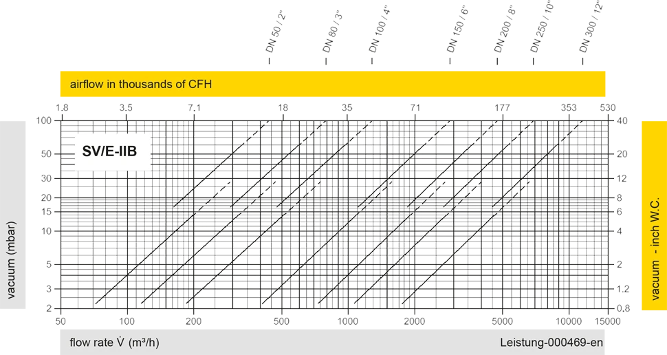
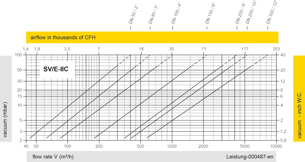
Los diagramas de flujo volumétrico han sido determinados con un banco de pruebas de caudal calibrado y certifi - cado por TÜV. El flujo volumétrico V. en [m³/h] y el CFH se refi eren a las condiciones estándar de referencia de aire según ISO 6358 (20°C, 1bar). La conversión a otras densidades y temperaturas están referidas en el Vol. 1: “Fundamentos Técnicos”.
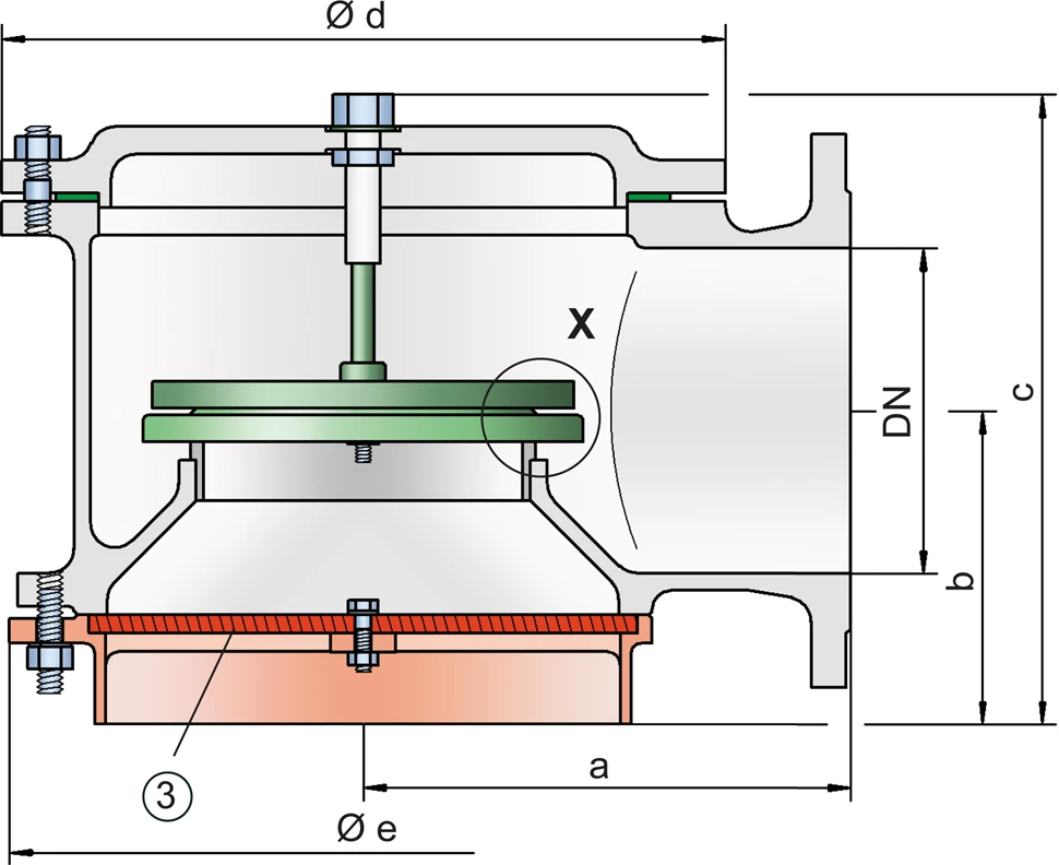

Detail X

Detail X