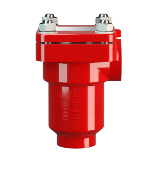
DR/ES, DN 1/4 - 3/4
In-Line Detonation Flame Arrester for stable detonations and deflagrations in right angle design, unidirectional
Features
Compact Design
Reduced Number of FLAMEFILTER® Discs
Fastest Disassembly and Assembly
Explosion Safety
Angle Bodied
State of the Art Protection
Spare Parts
Low Costs
Protects Against Deflagrations and Stable Detonations
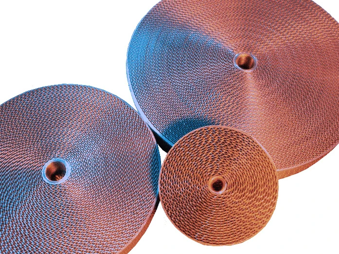
Main Component – PROTEGO® Flame Arrester Unit

Many Individual Certifications
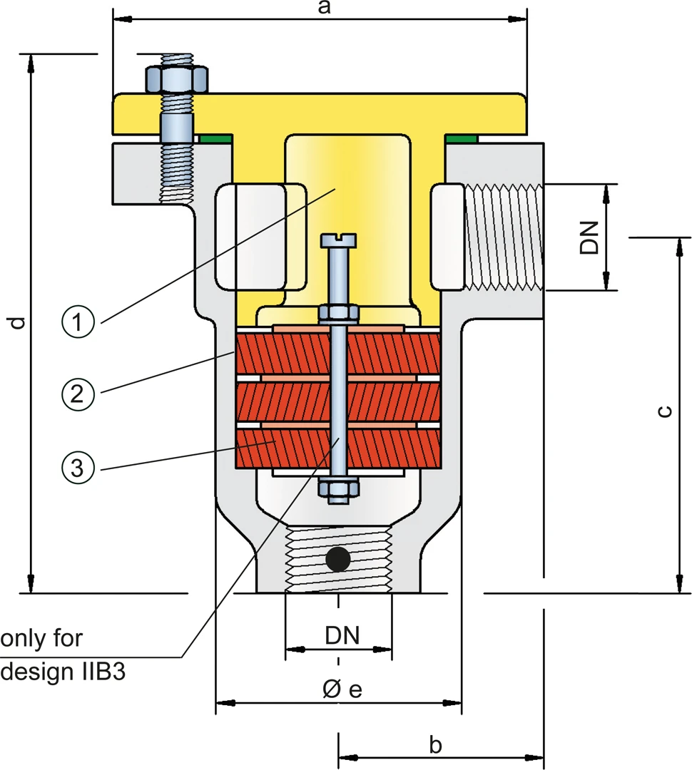
Dimensions
To select the nominal size (DN), please use the flow capacity charts on the following pages
| DN | G ¼" | G ½" | G ¾" |
| a | 48 / 1.89 | 70 / 2.76 | 80 / 3.15 |
| b | 35 / 1.38 | 40 / 1.57 | 47 / 1.85 |
| c | 70 / 2.76 | 75 / 2.95 | 87 / 3.43 |
| d | 108 / 4.25 | 115 / 4.53 | 135 / 5.31 |
| e | 34 / 1.34 | 50 / 1.97 | 60 / 2.36 |
Dimensions in mm / inches
Selection of explosion group
| MESG | Expl. Gr. (IEC / CEN) | Gas Group (NEC) |
| ≥ 0,65 mm | IIB3 | C |
| < 0,50 mm | IIC | B |
Special approvals upon request
Selection of max. operating pressure
| Expl. Gr. | DN | G ¼" | G ½" | G ¾" |
| IIB3 | Pmax | 1,2 / 17.4 | 1,2 / 17.4 | 1,2 / 17.4 |
| IIC | Pmax | 1,1 / 15.9 | 1,1 / 15.9 | 1,1 / 15.9 |
Pmax = maximum allowable operating pressure in bar / psi absolute, higher operating pressure upon request,
Expl. Gr. IIB3 covers Expl. Gr. IIA
Specification of max. operating temperature
| ≤ 60°C / 140°F | Tmaximum allowable operating temperature in °C |
| - | Designation |
higher operating temperatures upon request
Material selection for housing
| Design | B | C | D |
| Housing | Steel | Stainless Steel | Hastelloy |
| Cover with shock absorber* | Steel | Stainless Steel | Hastelloy |
| Gasket | PTFE | PTFE | PTFE |
| Flame arrester unit | A | A | B |
G ¼" only comes in design C and D
* G ¼" without shock absorber
Special materials upon request
Material combinations of flame arrester unit
| Design | A | B |
| FLAMEFILTER®* | Stainless Steel | Hastelloy |
| Spacer | Stainless Steel | Hastelloy |
* the FLAMEFILTER® are also available in the materi- als Tantalum, Inconel, Copper, etc. when the listed housing and cage materials are used.
Special materials upon request
Type of connection
| Pipe thread DIN ISO 228-1 | DIN |
other types of thread upon request
Flow Capacity Chart
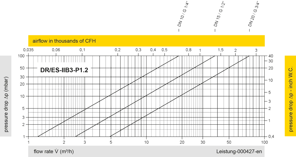
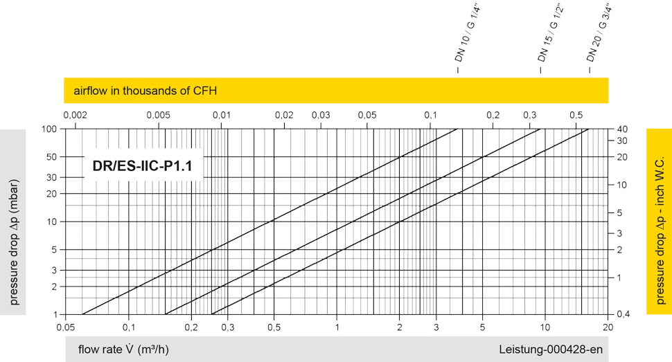
The flow capacity charts have been determined with a calibrated and TÜV certified flow capacity test rig. Volume flow V in (m³/h) and CFH refer to the standard reference conditions of air ISO 6358 (20°C, 1bar). For conversion to other densities and temperatures refer to Sec. 1: “Technical Fundamentals”.