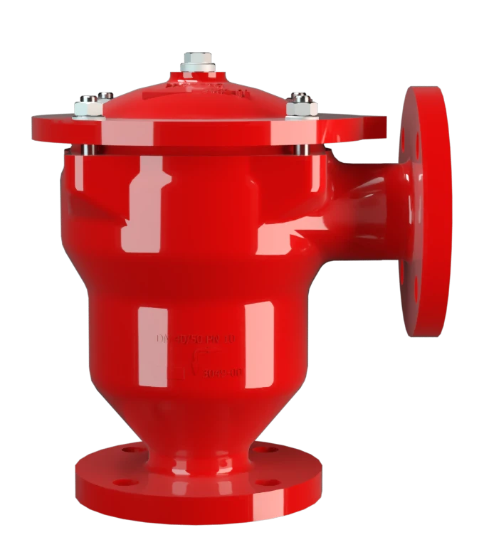
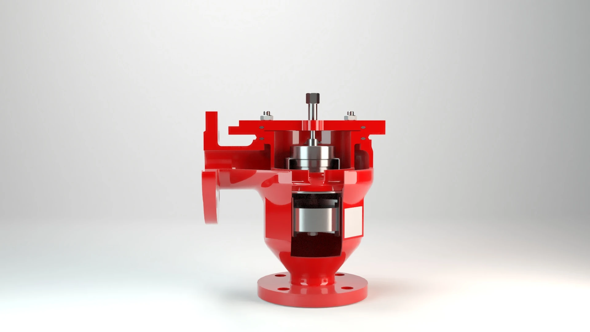
DR/ES-V
In-Line Detonation Flame Arrester with integrated pressure relief valve, for stable detonations and deflagrations in right angle design with shock absorber, unidirectional
Features
Integration into a Single Device
Optimal Use as Overflow Valve
Reduced Number of FLAMEFILTER® Discs
Fastest Disassembly and Assembly
Explosion Safety
Check Valve
Extended Application Range
Spare Parts
Protects Against Deflagration and Stable Detonation
In-Line Detonation Flame Arrester for Vent Headers

For Explosion Groups IIA to IIB3
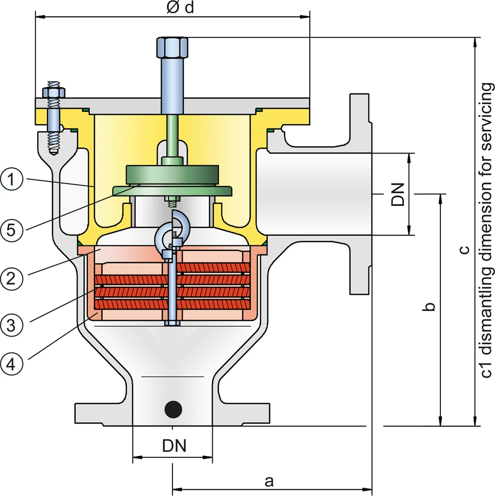
Dimensions
To select the nominal size (DN), please use the flow capacity charts on the following pages
| DN | 25 / 1" | 32 / 1¼“ | 40 / 1½“ | 50 / 2“ | 65 / 2½“ | 80 / 3“ | 100 / 4“ | 125 / 5“ | 150 / 6" | 200 / 8" |
| a | 125 / 4.92 | 125 / 4.92 | 153 / 6.02 | 155 / 6.10 | 198 / 7.80 | 200 / 7.87 | 250 / 9.84 | 332 / 13.07 | 335 / 13.19 | 425 / 16.73 |
| b | 140 / 5.51 | 140 / 5.51 | 183 / 7.20 | 185 / 7.28 | 223 / 8.78 | 225 / 8.86 | 290 / 11.42 | 357 / 14.06 | 360 / 14.17 | 505 / 19.88 |
| c | 237 / 9.33 | 237 / 9.33 | 305 / 12.01 | 305 / 12.01 | 395 / 15.55 | 395 / 15.55 | 460 / 18.11 | 575 / 22.64 | 575 / 22.64 | 863 / 33.98 |
| c1 | 345 / 13.58 | 345 / 13.58 | 410 / 16.14 | 410 / 16.14 | 530 / 20.87 | 530 / 20.87 | 615 / 24.21 | 790 / 31.10 | 790 / 31.10 | 1295 / 50.98 |
| d | 149 / 5.87 | 149 / 5.87 | 210 / 8.27 | 210 / 8.27 | 275 / 10.83 | 275 / 10.83 | 325 / 12.80 | 460 / 18.11 | 460 / 18.11 | 620 / 24.41 |
Dimensions in mm / inches
Selection of explosion group
| MESG | Expl. Gr. (IEC / CEN) | Gas Group (NEC) |
| > 0,90 mm | IIA | D |
| ≥ 0,65 mm | IIB3 | C |
Special approvals upon request
Selection of max. operating pressure
| Expl. Gr. | DN | 25 / 1" | 32 / 1¼" | 40 / 1½" | 50 / 2" | 65 / 2½" | 80 / 3" | 100 / 4" | 125 / 5" | 150 / 6" | 200 / 8" |
| IIA | Pmax | 4,0 / 58.0 | 4,0 / 58.0 | 4,0 / 58.0 | 4,0 / 58.0 | 2,9 / 42.1 | 2,9 / 42.1 | 2,0 / 29.0 | 2,0 / 29.0 | 2,0 / 29.0 | 1,2 / 17.4 |
| IIB3 | Pmax | 3,0 / 43.5 | 3,0 / 43.5 | 2,0 / 29.0 | 2,0 / 29.0 | 2,0 / 29.0 | 2,0 / 29.0 | 1,5 / 21.7 | 1,4 / 20.3 | 1,4 / 20.3 | 1,1 / 15.9 |
Pmax = maximum allowable operating pressure in bar / psi absolute, higher operating pressure upon request
Specification of max. operating temperature
| ≤ 60°C / 140°F | Tmaximum allowable operating temperature in °C |
| - | Designation |
higher operating temperatures upon request
Material selection for housing
| Design | B | C | D |
| Design | Steel | Stainless Steel | Hastelloy |
| Heating jacket (DR / ES-V-H-...) | Steel | Stainless Steel | Stainless Steel |
| Cover with shock absorber | Steel | Stainless Steel | Hastelloy |
| Gaskets | PTFE | PTFE | PTFE |
| Valve seat | Stainless Steel | Stainless Steel | Stainless Steel |
| Flame arrester unit | A | C, D | E |
The housing and the cover with shock absorber can also be delivered in steel with an ECTFE coating.
Special materials upon request
Material combinations of flame arrester unit
| Design | A | C | D | E |
| FLAMEFILTER® cage | Steel | Stainless Steel | Stainless Steel | Hastelloy |
| FLAMEFILTER®* | Stainless Steel | Stainless Steel | Hastelloy | Hastelloy |
| Spacer | Stainless Steel | Stainless Steel | Hastelloy | Hastelloy |
* the FLAMEFILTER® are also available in the materials Tantalum, Inconel, Copper, etc. when the listed housing and cage materials are used.
Special materials upon request
Selection of valve pallet
| Design | A | B | C |
| Pressure range | I | II | III |
| Set pressure [mbar] | +2.0 up to +3.5 | >+3.5 up to +14 | >+14 up to 35 |
| [inch W.C.] | +0.8 up to +1.4 | >+1.4 up to +5.6 | >+5.6 up to 14 |
| Valve pallet | Aluminium | Stainless Steel | Stainless Steel |
| Sealing | FEP | FEP | Metal to Metal |
Flange connection type
| EN 1092-1; Form B1 |
| ASME B16.5 CL 150 R.F. |
other connections upon request
Flow Capacity Chart
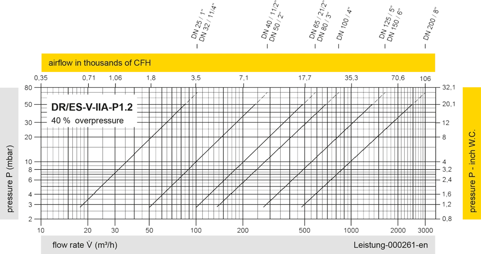
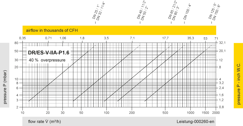
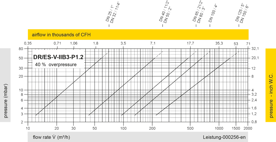
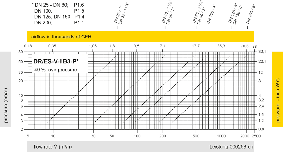
The flow capacity charts have been determined with a calibrated and TÜV certified flow capacity test rig. Volume flow V in (m³/h) and CFH refer to the standard reference conditions of air ISO 6358 (20°C, 1bar). For conversion to other densities and temperatures refer to Sec. 1: “Technical Fundamentals”.