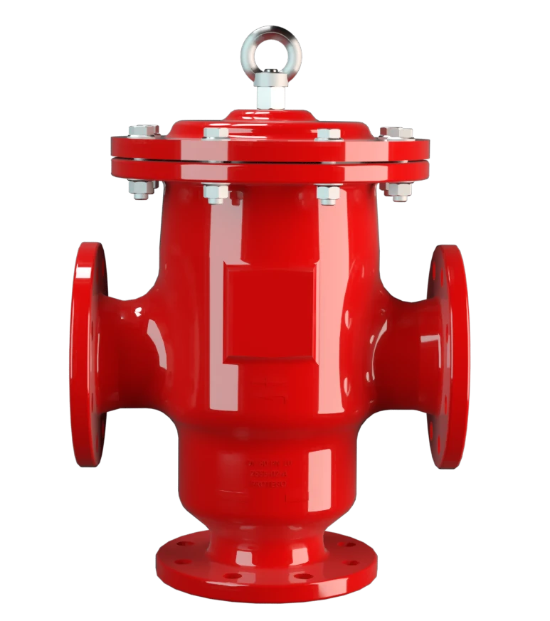
DV/ZU
Pressure and Vacuum Relief Valve, In-Line
Features
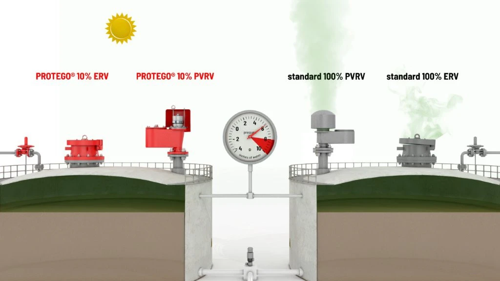
10% Technology
Extreme Tightness
Optimum Pressure Maintenance
High Flow Capacity
Separate Connections
Used in Explosion Hazardous Areas
Sturdy Housing Design
Pressure and Vacuum Relief Valve with Separate Connections for Pressure and Vacuum Breathing
Full Lift Technology
Advanced Manufacturing Technology
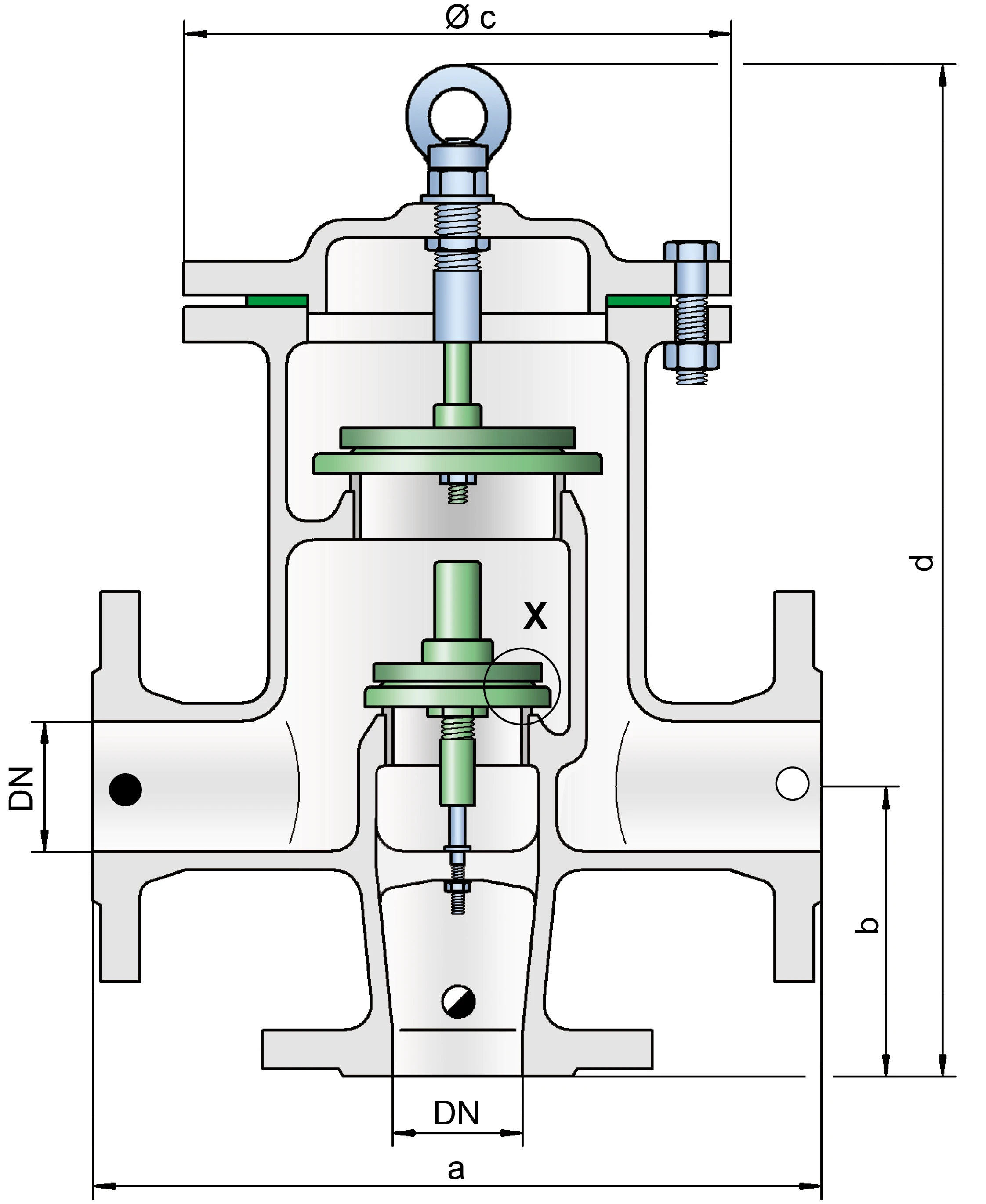
Dimensions
To select the nominal size (DN), please use the flow capacity charts on the following pages
| DN | 40 / 1½" | 50 / 2" | 65 / 2½" | 80 / 3" | 100 / 4" | 150 / 6" |
| a | 280 / 11.02 | 280 / 11.02 | 340 / 13.39 | 340 / 13.39 | 390 / 15.35 | 520 / 20.47 |
| b | 165 / 6.50 | 165 / 6.50 | 200 / 7.84 | 200 / 7.84 | 240 / 9.45 | 300 / 11.81 |
| c | 210 / 8.27 | 210 / 8.27 | 280 / 11.02 | 280 / 11.02 | 310 / 12.20 | 390 / 15.35 |
| d | 440 / 17.32 | 440 / 17.32 | 495 / 19.49 | 495 / 19.49 | 590 / 23.23 | 715 / 28.15 |
Dimensions in mm / inches
Larger sizes upon request
Dimensions for pressure and vacuum relief valve with heating jacket upon request
Material selection for housing
| Design | A | B |
| Housing | Steel | Stainless Steel |
| Heating jacket (DV / ZU-H-...) | Steel | Stainless Steel |
| Valve seat | Stainless Steel | Stainless Steel |
| Gasket | PTFE | PTFE |
Option: Housing with ECTFE-lining
Special materials upon request
Material selection for pressure valve pallet
| Design | A | B | C | D |
| Pressure range [mbar] [inch W.C.] | +2.0up to +3.5 +0.8up to +1.4 | >+3.5up to +14 >+1.4 up to +5.6 | >+14up to +60 >+5.6up to +24 | >+14up to +60 >+5.6up to +24 |
| Valve pallet | Aluminium | Stainless Steel | Stainless Steel | Stainless Steel |
| Sealing | FEP | FEP | Metal to Metal | PTFE |
Special materials upon request
For higher set pressures refer to type DV/ZU-F.
Material selection for vacuum valve pallet
| Design | A | B | C | D | E | F |
| Pressure range [mbar] [inch W.C.] | -3.5up to -5.0 -1.4up to -2.0 | <-5.0 up to -14 <-2.0up to -5.6 | <-14up to -35 <-5.6 up to -14 | <-35 up to -50 <-14 up to -20 | <-14 up to -35 <-5.6 up to -14 | <-35 up to -50 <-14 up to -20 |
| Valve pallet | Aluminium | Stainless Steel | Stainless Steel | Stainless Steel | Stainless Steel | Stainless Steel |
| Sealing | FEP | FEP | Metal to Metal | Metal to Metal | PTFE | PTFE |
Special materials and lower set vacuum upon request.
Flange connection type
| EN 1092-1; Form B1 |
| ASME B16.5 CL 150 R.F. |
other types upon request
Flow Capacity Chart
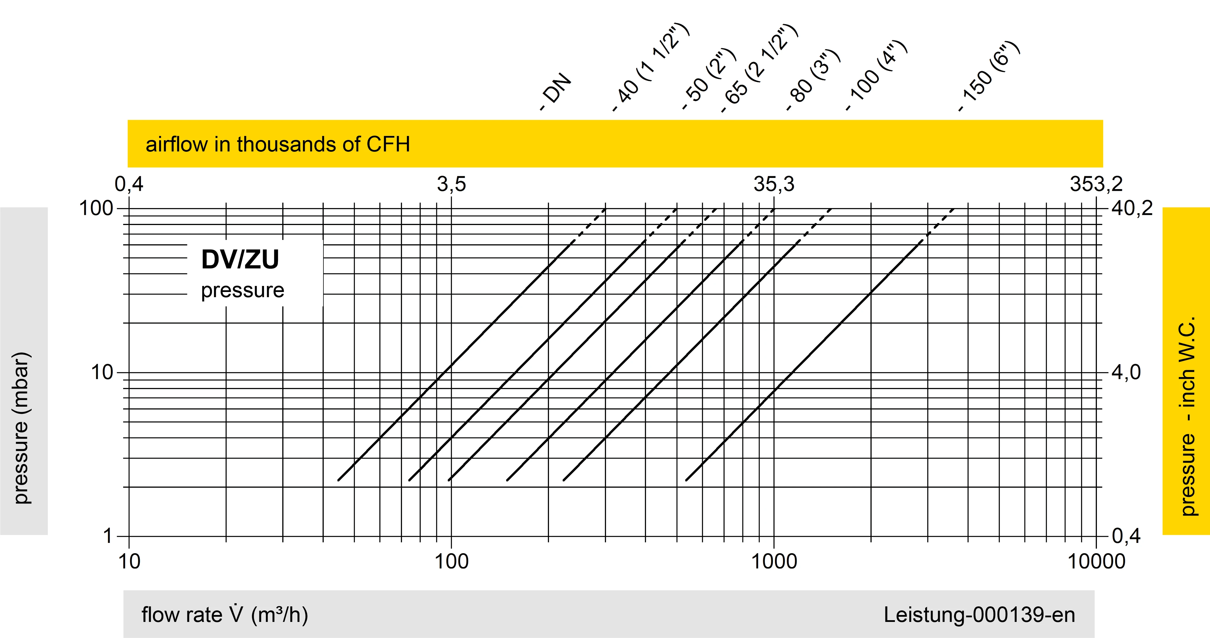
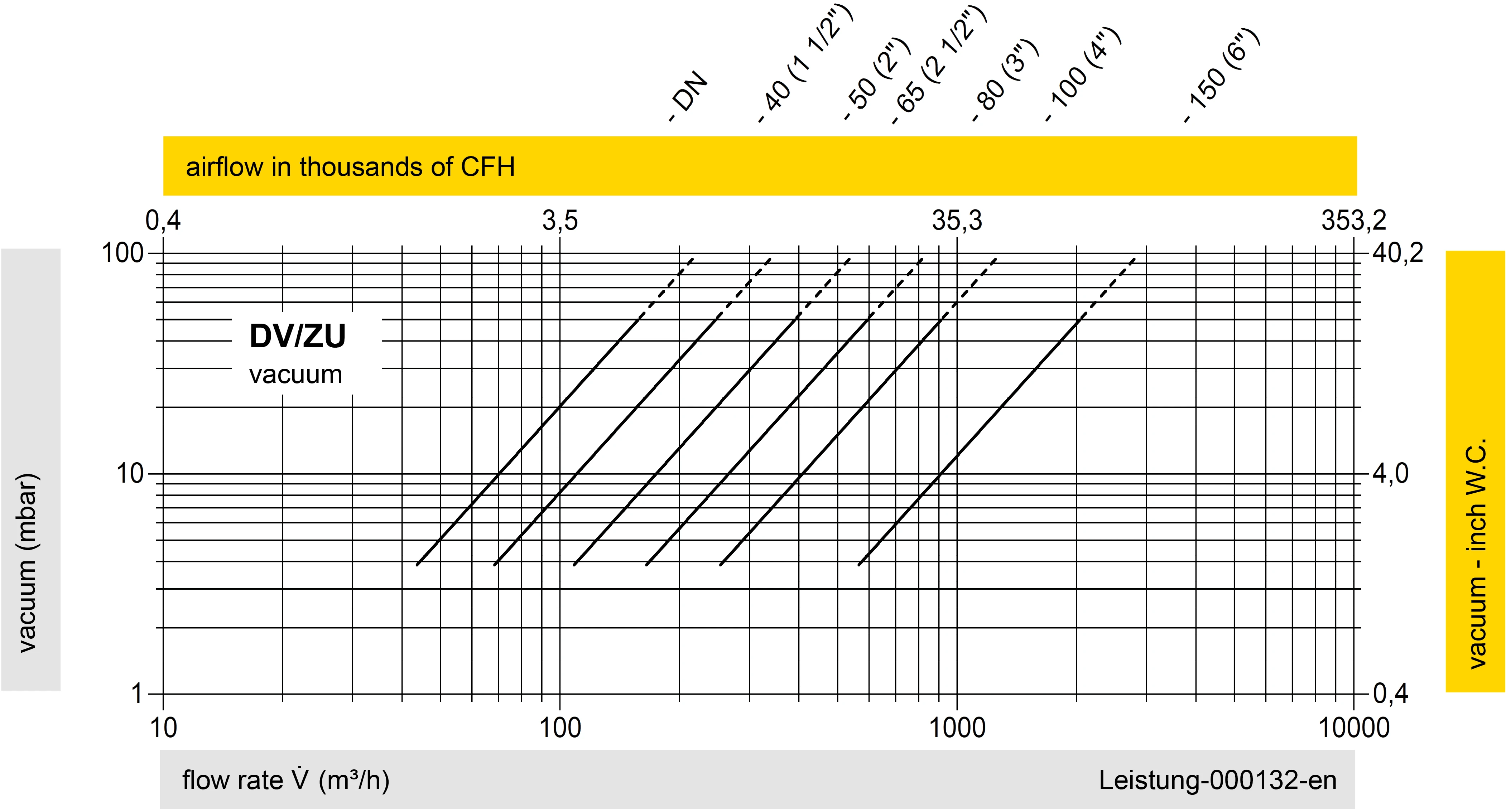
The flow capacity charts have been determined with a calibrated and TÜV certified flow capacity test rig. Volume flow V in (m³/h) and CFH refer to the standard reference conditions of air ISO 6358 (20°C, 1bar). For conversion to other densities and temperatures refer to Sec. 1: “Technical Fundamentals”.
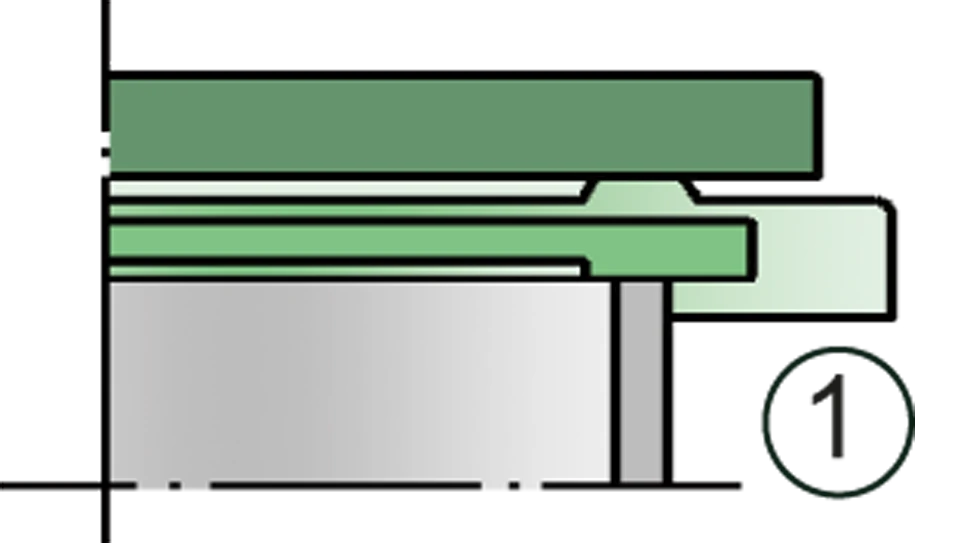
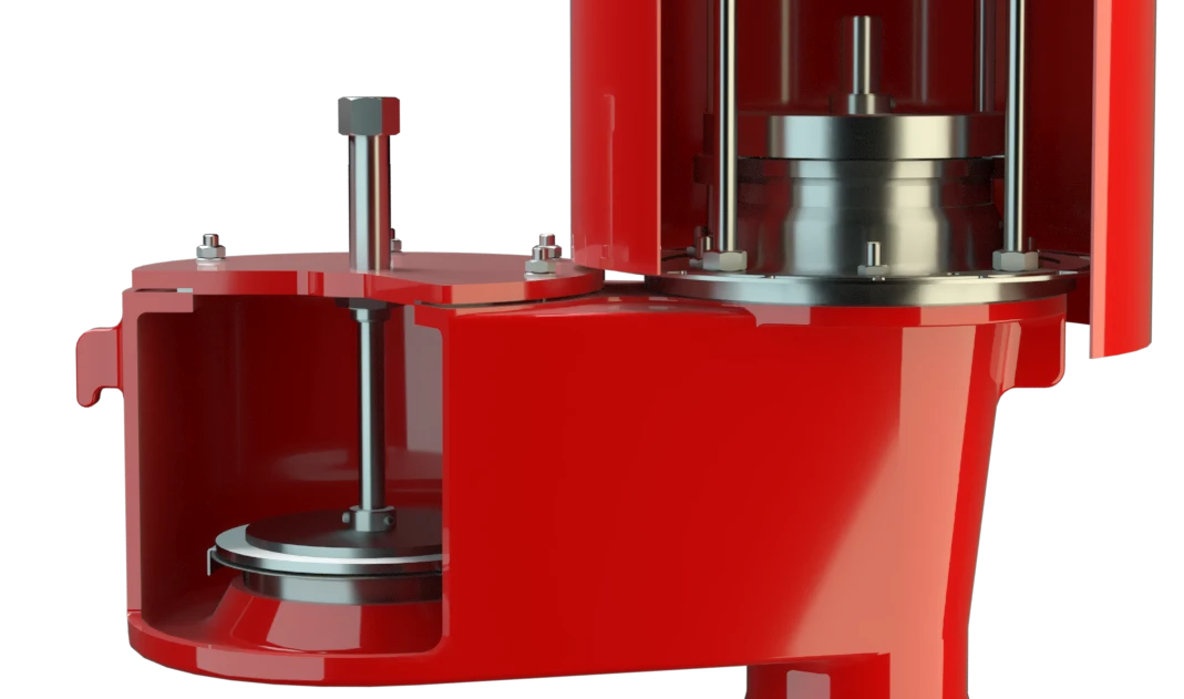
Detail X

Detail X

Tank connection

Inbreathing

Outbreathing