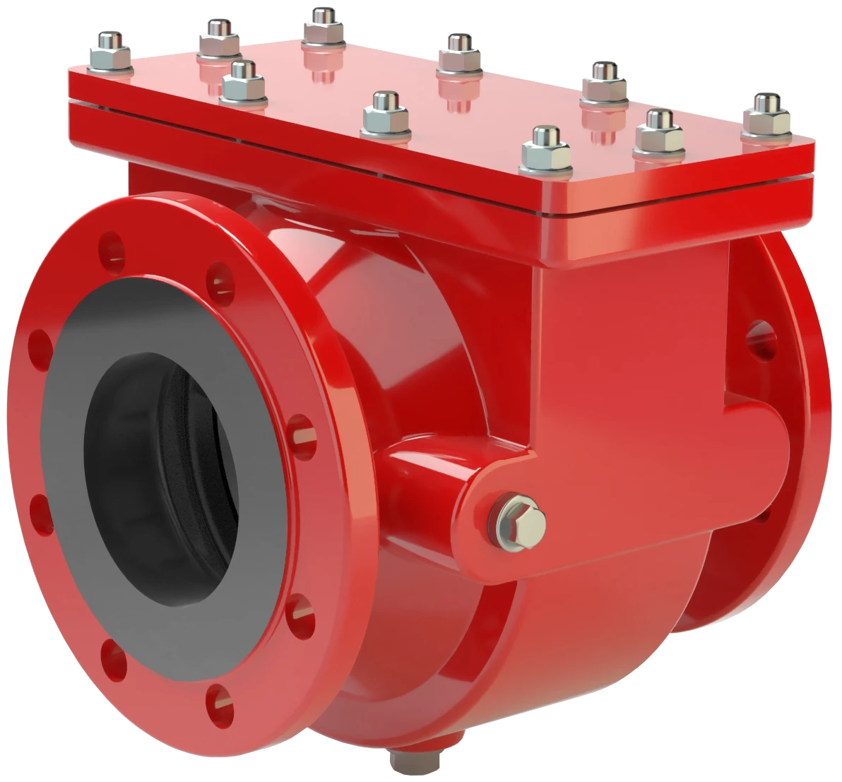
FA-CN-IIA1
In-Line Deflagration Flame Arrester for biogas, sewage gas and landfill gas, concentric design, bidirectional
Features
Extended Application Range
Compact Design
Spare Parts
Modular Design
Low Costs
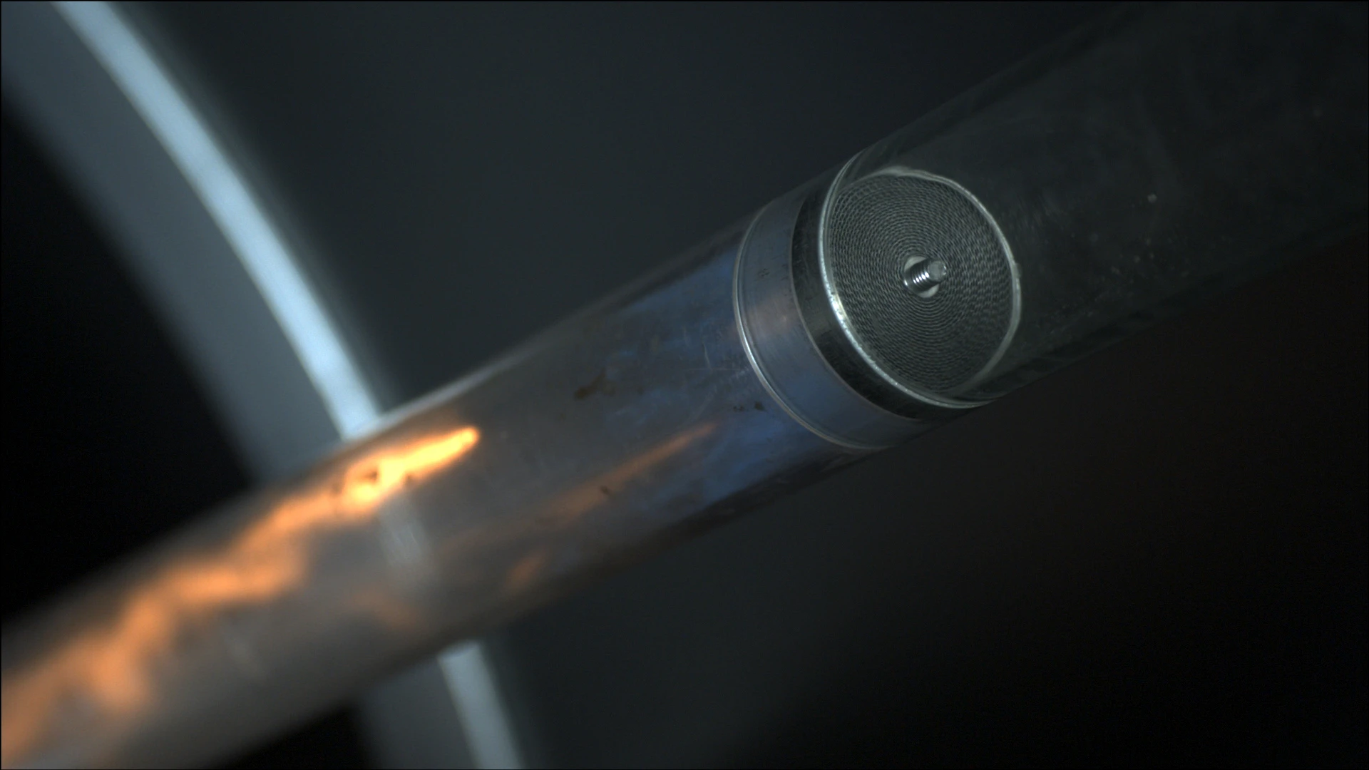
Bi-Directional Flame Transmission
Compact and Maintenance-Friendly Endurance-Burning-Proof In-Line Device
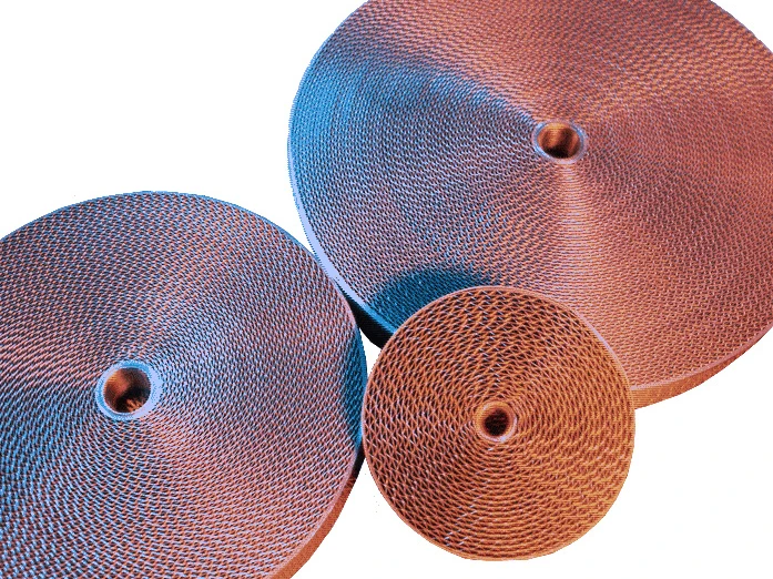
Main Component – PROTEGO® Flame Arrester Unit
For Explosion Group IIA1

Many Individual Certifications
Dimensions
To select the nominal size (DN), please use the flow capacity charts on the following pages
| DN | 40 / 1½" | 50 / 2" | 65 / 2½" | 80 / 3" | 100 / 4" | 125 / 5" | 150 / 6" | 200 / 8" | 250 / 10" | 300 / 12" |
| a | 210 / 8.27 | 215 / 8.46 | 235 / 9.25 | 240 / 9.45 | 265 / 10.43 | 305 / 12.01 | 310 / 12.20 | 300 / 11.81 | 320 / 12.60 | 350 / 13.78 |
| b | 105 / 4.13 | 105 / 4.13 | 105 / 4.13 | 132 / 5.2 | 150 / 5.91 | 197 / 7.75 | 197 / 7.75 | 220 / 8.66 | 260 / 10.24 | 295 / 11.61 |
| c | 200 / 7.87 | 200 / 7.87 | 260 / 10.24 | 260 / 10.24 | 308 / 12.13 | 415 / 16.34 | 415 / 16.34 | 446 / 17.56 | 520 / 20.47 | 600 / 23.62 |
| d | 130 / 5.12 | 130 / 5.12 | 185 / 7.28 | 185 / 7.28 | 220 / 8.66 | 310 / 12.20 | 310 / 12.20 | 355 / 13.98 | 420 / 16.54 | 490 / 19.29 |
Dimensions in mm / inches
Selection of explosion group
| MESG | Expl. Gr. (IEC / CEN) |
| > 1.14 mm | IIA1 (I) |
Special approvals upon request
Selection of max. operating pressure
| DN | 40 / 1½" | 50 / 2" | 65 / 2½" | 80 / 3" | 100 / 4" | 125 / 5" | 150 / 6" | 200 / 8" | 250 / 10" | 300 / 12" |
| Pmax | 2.0 / 29.0 | 2.0 / 29.0 | 1,6 / 23.2 | 1,6 / 23.2 | 1,6 / 23.2 | 1,6 / 23.2 | 1,6 / 23.2 | 1,6 / 23.2 | 1,6 / 23.2 | 1,6 / 23.2 |
| Pmax | 2,5 / 36.3 | 2,5 / 36.3 | 2,5 / 36.3 | 2,5 / 36.3 | 2,5 / 36.3 | 2,5 / 36.3 | 2,5 / 36.3 | 2,5 / 36.3 | ||
| Pmax | 4,5 / 65.3 | 4,5 / 65.3 | 4,5 / 65.3 | 4,5 / 65.3 | 4,5 / 65.3 | 4,5 / 65.3 | 4,5 / 65.3 | |||
| Pmax | 5 / 72.5 | 5 / 72.5 |
Pmax = maximum allowable operating pressure in bar / psi absolute, higher operating pressure upon request
Specification of max. operating temperature
| ≤ 60°C / 140°F | Tmaximum allowable operating temperature in °C |
| - | Designation |
higher operating temperatures upon request
Material selection
| Design | A | B | |
| Housing | Steel | Stainless Steel | |
| Cover | Steel | Stainless Steel | |
| Gasket | WS 3822 * | PTFE | |
| Flame arrester unit | Stainless Steel | Stainless Steel |
* for devices exposed to temperatures above 150°C / 302°F (T150), gaskets made of PTFE.
Special materials upon request
Flange connection type
| EN 1092-1; Form B1 |
| ASME B16.5 CL 150 R.F. |
other connections upon request
Flow Capacity Chart
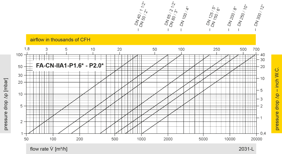
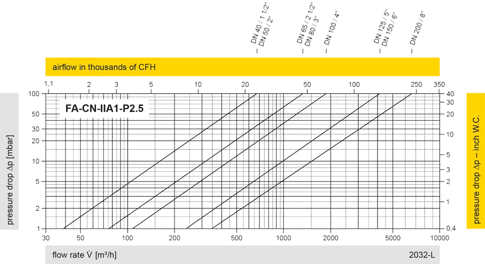
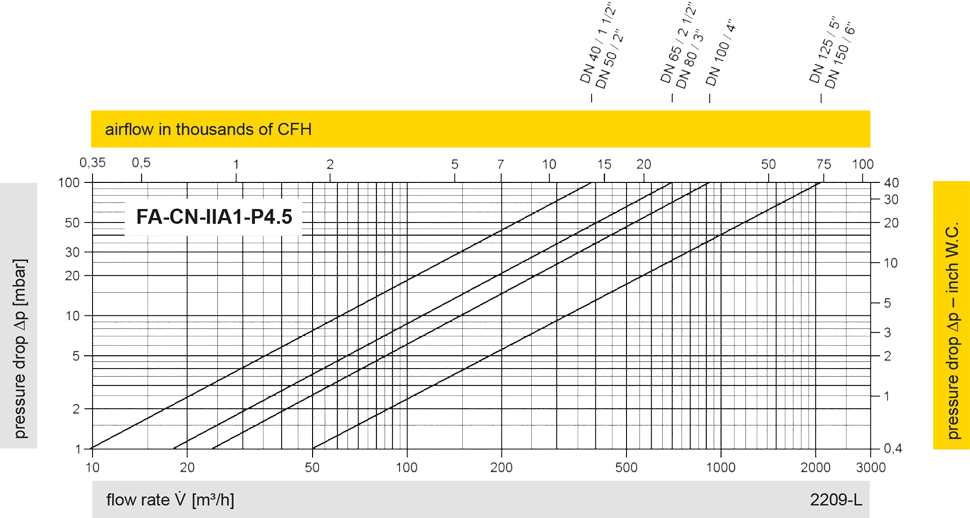
The flow capacity charts have been determined with a calibrated and TÜV certified flow capacity test rig. Volume flow V in (m³/h) and CFH refer to the standard reference conditions of air ISO 6358 (20°C, 1bar). For conversion to other densities and temperatures refer to Sec. 1: “Technical Fundamentals”.