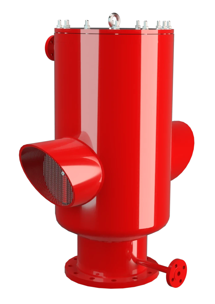
SV/T-0-H
Vacuum Relief Valve in a special heat jacketed design
Features
Extreme Tightness
Resulting in Lowest Possible Product Losses and Reduced Environmental Pollution
Flow Capacity
Optimized Flow Capacity
Guided Valve Pallet
Valve Pallet Is Guided Inside the Housing to Protect Against Harsh Weather Conditions
Used in Explosion Hazardous Areas
can Be Used in Explosion Hazardous Areas
Heating Jackets
Complete Heating Jacket Up to the Flange to Avoid Ice Build-Up
Heatable Valve Cover Available
Available in a Special Design With a Heatable Valve Cover
Sturdy Housing Design
(PN 10 and PN 16)
Lifting Device
Available in a Special Design With Lifting Device (for Ships)
Function and Description
Highly Developed Vacuum Relief Valve
The SV/T-0-H Type PROTEGO® valve is a highly developed vacuum relief valve with a valve housing that is equipped with a heating jacket that can be heated up to the flange. It is primarily used as a device for in-breathing in tanks, containers, and process engineering equipment under difficult operating conditions. This includes extreme weather conditions or products that tend to form polymers at certain temperatures, stick together, or form deposits that negatively influence function (such as bitumen, tar, dust). The valve offers reliable protection against vacuum and prevents air intake almost up to the set vacuum.
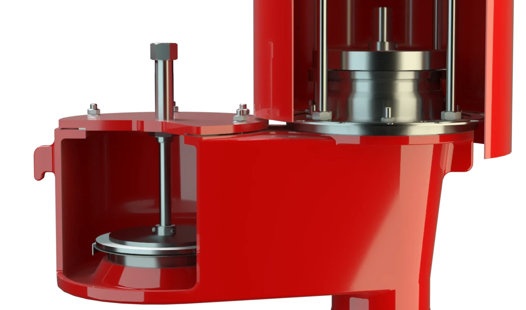
Advanced Manufacturing Technology
When the set vacuum is reached, the valve starts to open and reaches full lift within a 40% vacuum increase. Up to the set vacuum, the tank vacuum is maintained with a seal that is far superior to the conventional standard due to the highly developed manufacturing technology. This feature is achieved by valve seats made of high quality stainless steel with precisely lapped valve pallets and a sturdy housing design. After the vacuum is released, the valve re-seats and again provides a tight seal.
Product Data
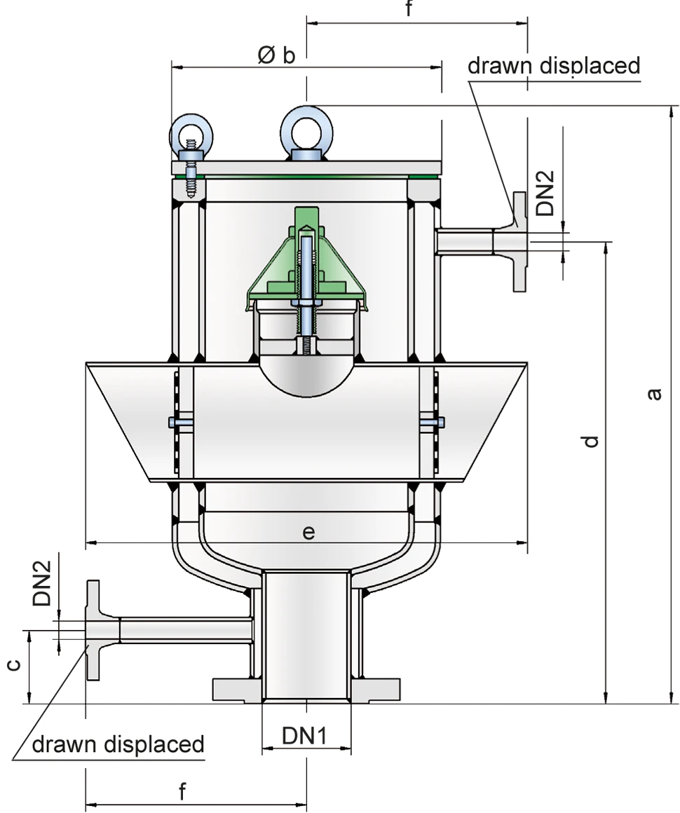
Dimensions
To select the nominal size (DN), use the flow capacity chart on the following page
| DN1 | 80* / 3"* | 100 / 4" | 150 / 6" | 200 / 8" | 250 / 10" |
| DN2 | 15 / ½" | 15 / ½" | 15 / ½" | 15 / ½" | 15 / ½" |
| a | 570 / 22.44 | 570 / 22.44 | 720 / 28.35 | 920 / 36.22 | 1050 / 41.34 |
| b | 275 / 10.83 | 275 / 10.83 | 355 / 13.98 | 405 / 15.94 | 508 / 20.00 |
| c | 70 / 2.76 | 70 / 2.76 | 60 / 2.36 | 70 / 2.76 | 70 / 2.76 |
| d | 440 / 17.32 | 440 / 17.32 | 590 / 23.23 | 790 / 31.10 | 920 / 36.22 |
| e | 450 / 17.72 | 450 / 17.72 | 650 / 25.59 | 750 / 29.53 | 950 / 37.40 |
| f | 225 / 8.86 | 225 / 8.86 | 260 / 10.24 | 300 / 11.91 | 350 / 13.78 |
Dimensions in mm / inches
* also available with special flange DN 50 / 2''
Material selection for housing
| Design | A | B |
| Housing | Steel | Stainless Steel |
| Heating jacket | Steel | Stainless Steel |
| Valve seat | Stainless Steel | Stainless Steel |
| Sealing | PTFE | PTFE |
Special materials upon request
Material selection for vacuum valve pallet
| Design | A | B | C |
| Vacuum range [mbar] [inch W.C.] | -7,0 up to -25 -2.8 up to -10 | -10 up to-30 -4.0 up to -12 | -30 up to-50 -12 up to -20 |
| Valve pallet | Aluminium | Stainless Steel | Stainless Steel |
| Valve pallet hood | Stainless Steel | Stainless Steel | Stainless Steel |
| Sealing | Metal to Metal | Metal to Metal | Metal to Metal |
Special materials and other vacuum settings are available upon request
Flange connection type
| EN 1092-1; Form B1 |
| ASME B16.5 CL 150 R.F. |
other types upon request
Flow Capacity Chart
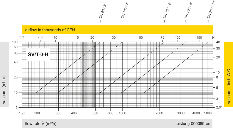
The flow capacity charts have been determined with a calibrated and TÜV certified flow capacity test rig. Volume flow V in (m³/h) and CFH refer to the standard reference conditions of air ISO 6358 (20°C, 1bar). For conversion to other densities and temperatures refer to Sec. 1: “Technical Fundamentals”.