PM-HF
Pressure/Vacuum Relief Valve Pilot-operated diaphragm valve
Features
Kit de teste de campo
Conexão para teste de campo e kit disponíveis sob consulta
Tecnologia de 10%
para aumento mínimo de pressão até a abertura total
Operado por piloto
Controlado por válvula de controle resistente à corrosão (válvula piloto)
Estanqueidade extrema
Resulta nas menores perdas possíveis de produto e na redução do impacto ambiental
Baixas emissões
Pequenas quantidades da substância armazenada no tanque são liberadas para a atmosfera quando a válvula é aberta
Capacidade de vazão
Capacidade de vazão otimizada
Uso em áreas com risco de explosão
Pode ser utilizado em áreas com risco de explosão
Alta estabilidade
Construção da válvula estável e aprimorada
Function and Description
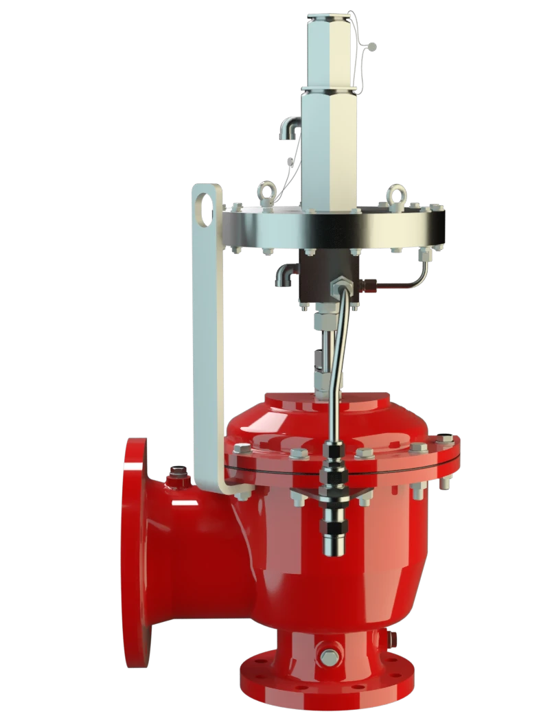
Combined Pressure and Vacuum Relief Valve
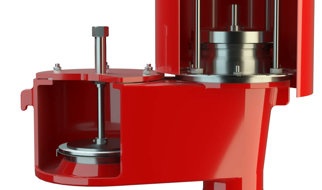
The PROTEGO® Type PM-HF pilot-controlled diaphragm valve is a highly developed valve for pressure and vacuum relief. Primarily used as a device for outbreathing in tanks, vessels, and process engineering equipment it also offers reliable protection from vacuum and overpressure. It prevents intake of air and unacceptable product vapor loss up to and until the set-to-operate pressure is reached. The valve can be used as an inbreathing device as well. In such an application, the main valve is directly controlled when exposed to a vacuum, i.e. it functions as a weight-loaded diaphragm valve.
Tank Pressure Controls the Pilot Valve
The main valve is controlled by a pilot valve. The latter in turn is controlled by the tank pressure. A small amount fluid stored in the tank released into the atmosphere by the pilot when the valve opens. The set-to-operate pressure is adjusted on the pilot valve by increasing or decreasing (as appropriate) the tension of a spring.
Extreme Tightness
As the working pressure rises, the closing force acting on the main valve increases, i.e. the valve's tight-sealing is enhanced until the set-to-operate pressure is reached, thus preventing leakage. Once the valve has commenced to lift it opens fully within a 10% pressure rise or the opening pressure difference and the nominal volumetric fl ow is discharged through a fully open valve. If and when this level is exceeded the pressure increase will follow the performance curve (Δp/V.curve). From set pressure to full capacity (fully open valve) the pressure increase is 100% in case of vacuum venting/inbreathing function.
Advanced Manufacturing Technology
Due to the sophisticated manufacturing technology, the tank pressure is maintained up to the set-to-operate pressure, with seal-tight requirements far above common standards being met. This feature is achieved through valve seats made of high-grade stainless steel with precisely ground valve pallets. Once the excess pressure is relieved or pressure below atmospheric balanced out, the valve reseats and seals tight again.
Product Data
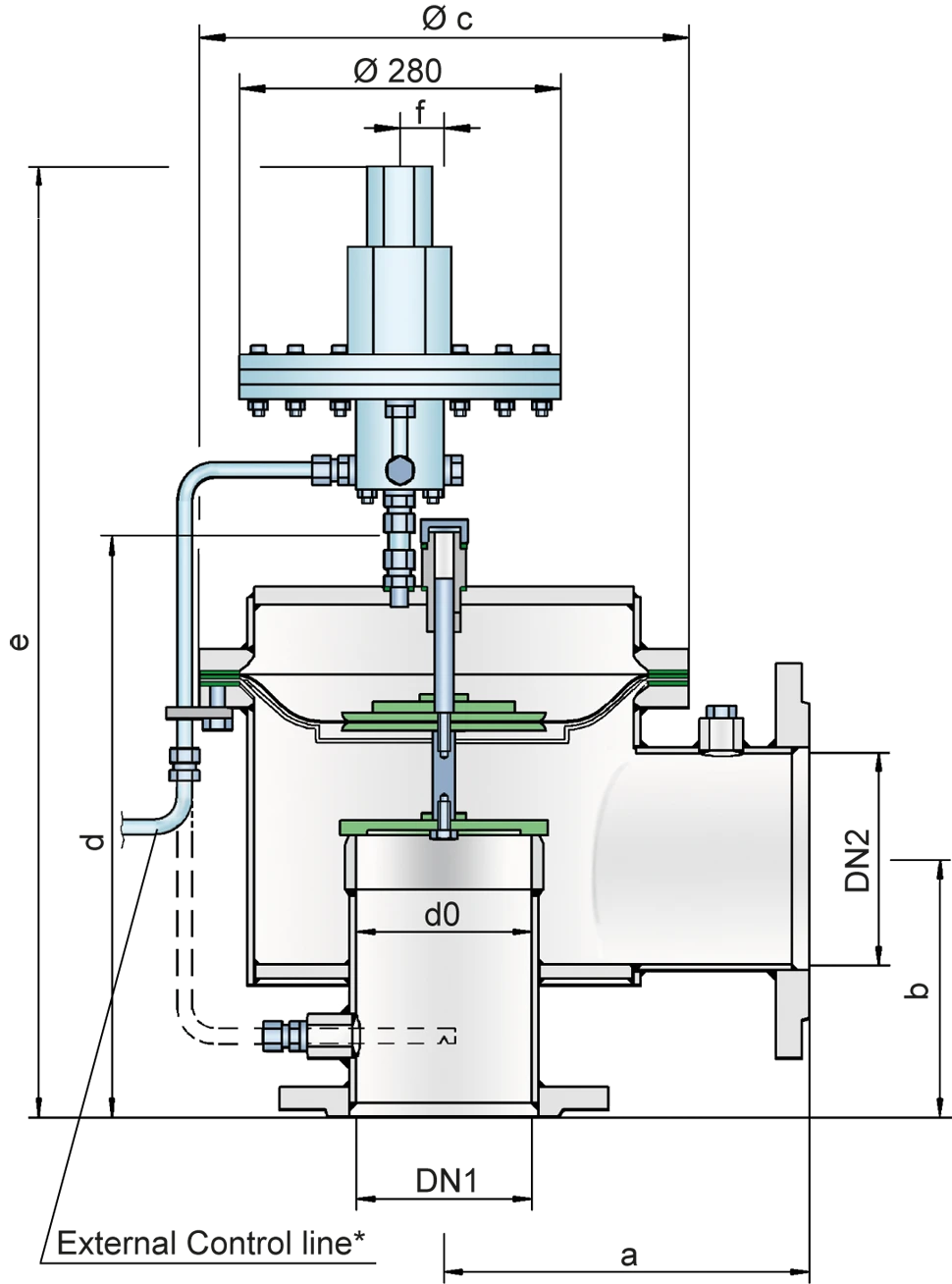
Tabela de dimensões
Para escolher o diâmetro nominal (DN), veja os diagramas de vazão nas páginas seguintes
| DN1 | 80 / 3" | 100 / 4" | 150 / 6" | 200 / 8" | 250 / 10" | 300 / 12" | 300 / 12" |
| DN2 | 100 / 4" | 150 / 6" | 200 / 8" | 250 / 10" | 300 / 12" | 350 / 14" | 400 / 16" |
| a | 225 / 8.86 | 250 / 9.87 | 325 / 12.80 | 375 / 14.76 | 450 / 17.72 | 500 / 19.69 | 500 / 19.69 |
| b | 150 / 5.91 | 175 / 6.89 | 225 / 8.86 | 250 / 9.84 | 270 / 10.63 | 300 / 12.81 | 325 / 12.80 |
| c | 275 / 10.83 | 330 / 12.99 | 445 / 17.52 | 550 / 21.65 | 665 / 26.18 | 785 / 30.91 | 785 / 30.91 |
| d | 376 / 14.80 | 429 / 16.89 | 536 / 21.10 | 607 / 23.90 | 678 / 26.69 | 796 / 31.34 | 846 / 33.31 |
| e | 763 / 30.04 | 770 / 30.31 | 923 / 36.34 | 977 / 38.46 | 1052 / 41.42 | 1173 / 46.18 | 1223 / 48.15 |
| f | 35 / 1.38 | 40 / 1.57 | 40 / 1.57 | 50 / 1.97 | 50 / 1.97 | 50 / 1.97 | 50 / 1.97 |
Dimensões em mm
Seleção do material do corpo
| Execução | A | B |
| Corpo | Alumínio | Aço inoxidável |
| Sedes de válvulas | Aço inoxidável | Aço inoxidável |
| Vedação | KL-C-4106 | KL-C-4106 |
| Proteção do diafragma principal | Aço inoxidável | Aço inoxidável |
| Tubos de comando | Aço inoxidável | Aço inoxidável |
| Corpo da unidade piloto | Alumínio | Alumínio / Aço inoxidável |
| Diafragma piloto | FEP | FEP |
Materiais especiais sob solicitação
Coefficient of Discharge
| DN1 | 80 / 3" | 100 / 4" | 150 / 6" | 200 / 8" | 250 / 10" | 300 / 12" | 300 / 12" |
| DN2 | 100 / 4" | 150 / 6" | 200 / 8" | 250 / 10" | 300 / 12" | 350 / 14" | 400 / 16" |
| do | 81 | 107 | 160 | 208 | 260 | 310 | 310 |
| K | 0,68 | 0,68 | 0,63 | 0,59 | 0,58 | 0,54 | 0,61 |
DN1 = Size Inlet
DN2 = Size Outlet
d0 = Orifice Diameter (mm / inches)
K = Coefficient of Discharge
Tipo de conexão flangeada
| EN 1092-1; Form B1 |
| ASME B16.5 CL 150 R.F. |
Outras conexões sob solicitação
Diagrama de vazão
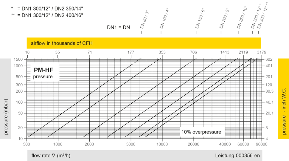
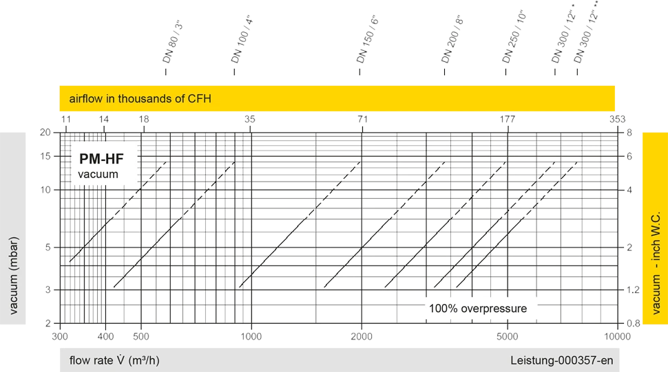
Este diagrama de vazão foi determinado em uma bancada de medição de vazão calibrada e certificada pela TÜV. A vazão V em m³/h se refere ao estado técnico padrão de ar, conforme ISO 6358 (20°C, 1bar). Para conversão em outras densidades e temperaturas, veja o cap. 1: Bases técnicas.